Ken Roberts
2007-06-12 15:52:28 UTC
Hey.
I have a project. I want to be able to lift my UH-18sp while in the
garage.
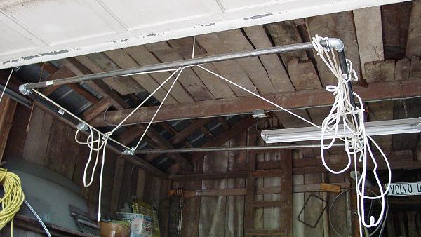
I built a gantry crane similar to these: http://www.gorbel.com/pdfs/Jib%20Brochure/Gantry.pdf
A is 10', B is 6'2", C is 6'10", D is about 9'4". I have a chain hoist
on it, everything works fine. The crane is that short so it fits under
my garage door. I'm just telling you so you can see what the project
is all about.
The garage door is 6'11" high, and the ceiling is 8' with stuff like
lights hanging down.
The problem is, by the time I have a chain hoist on it it's all too
low to tie a strap around the craft and pick it up. I need a sort of
specially designed harness, and matching hard points on the hull.
Before anyone suggests it, a cherry picker will not work. The only
place you could get wheels under is from the back, and the wheel plus
leg can't be higher than about 2". And then I'd need to disassemble
the entire tail structure and guards in order to get the arm where it
would do some good. Chances are, I'll need to use this device every
time I hover, and I'm not interested in a 3-hour process.
The goals of this harness are:
1. Pick the hovercraft up with just one man (me), anywhere, to work on
it. (using jack stands of course)
2. Put the hovercraft on the trailer and take it off quickly, without
starting an engine, disassembling, etc.
3. Avoid annoying the neighbors at odd hours with an engine, on nights
right before the rally.
I have a couple options I can think of:
2x6 wood dual-beam approach ------------------------------
I can make 2x6 beams about 8' long. On the back, they attach to the
engine stand. On the front, they attach to carriage bolts which go
through the hull and stick up under the dashboard. There would be a
plywood disc or rectangle on top and bottom to handle additional
stresses. Right at the balance point, I attach a cross member
(probably steel) to which the hoist hook attaches. The cross member
would be about at seat level.
Advantages
1. Cheap.
2. I could get the hook point about level with the bottom of the
padding on the seat. This gives me about 24" of vertical travel with
the hook.
Disadvantages
1. Bulky.
2. Wood warps, so what works one time might fail later.
3. Wood boards in my garage have a tendency to turn into something
else.
Steel dual-beam frame approach ------------------------------
This would be the same as the wood dual-beam approach, only made of
steel.
Advantages
1. Hook point is about the same as above.
2. Steel is much more reliable than wood in terms of warping.
3. Easier to make exactly what I need.
Disadvantages
1. More expensive than boards.
2. Steel square tube in my garage has a tendency to turn into
something else.
Steel single-beam approach ------------------------------
This would be a steel harness that bolts to my engine stand, and
another harness that bridges the hard points under the dash. Then a
single beam would run down the middle of the seat to connect the two
harnesses.
Advantages
1. Use less steel
2. Fewer parts to trip over in the garage.
Disadvantages
1. Hook point is higher than the dual beam approach.
Composite sandwich tunnel approach ------------------------------
This would be completely different. The standard UH tunnel that runs
down the center of the cockpit would be modified as follows:
1. Through-hull lag bolts would have a plywood disc on the bottom and
a high-strength support on top which attaches to the tunnel wall.
2. The tunnel wall would become a composite sandwich for strength.
3. For an attachment point, a hole is drilled on each side of the
tunnel and a bar goes through.
Advantages
1. Integrated into the hovercraft for the most part, so it's easier to
set up and take down, if that has to be done at all.
2. Lighter weight overall.
3. Hook point is below the seat, lowest of all approaches I can think
of.
Disadvantages
1. Cost? Not sure on this, might not cost any more than anything else
I'm talking about.
2. I don't know how good this composite structure would have to be.
3. I don't know how much of the underside I would have to strengthen
in order to keep the thing from delaminating.
------------------------------
I'd like to hear from you engineers out there, for any ideas or
suggestions.
I have a project. I want to be able to lift my UH-18sp while in the
garage.
I built a gantry crane similar to these: http://www.gorbel.com/pdfs/Jib%20Brochure/Gantry.pdf
A is 10', B is 6'2", C is 6'10", D is about 9'4". I have a chain hoist
on it, everything works fine. The crane is that short so it fits under
my garage door. I'm just telling you so you can see what the project
is all about.
The garage door is 6'11" high, and the ceiling is 8' with stuff like
lights hanging down.
The problem is, by the time I have a chain hoist on it it's all too
low to tie a strap around the craft and pick it up. I need a sort of
specially designed harness, and matching hard points on the hull.
Before anyone suggests it, a cherry picker will not work. The only
place you could get wheels under is from the back, and the wheel plus
leg can't be higher than about 2". And then I'd need to disassemble
the entire tail structure and guards in order to get the arm where it
would do some good. Chances are, I'll need to use this device every
time I hover, and I'm not interested in a 3-hour process.
The goals of this harness are:
1. Pick the hovercraft up with just one man (me), anywhere, to work on
it. (using jack stands of course)
2. Put the hovercraft on the trailer and take it off quickly, without
starting an engine, disassembling, etc.
3. Avoid annoying the neighbors at odd hours with an engine, on nights
right before the rally.
I have a couple options I can think of:
2x6 wood dual-beam approach ------------------------------
I can make 2x6 beams about 8' long. On the back, they attach to the
engine stand. On the front, they attach to carriage bolts which go
through the hull and stick up under the dashboard. There would be a
plywood disc or rectangle on top and bottom to handle additional
stresses. Right at the balance point, I attach a cross member
(probably steel) to which the hoist hook attaches. The cross member
would be about at seat level.
Advantages
1. Cheap.
2. I could get the hook point about level with the bottom of the
padding on the seat. This gives me about 24" of vertical travel with
the hook.
Disadvantages
1. Bulky.
2. Wood warps, so what works one time might fail later.
3. Wood boards in my garage have a tendency to turn into something
else.
Steel dual-beam frame approach ------------------------------
This would be the same as the wood dual-beam approach, only made of
steel.
Advantages
1. Hook point is about the same as above.
2. Steel is much more reliable than wood in terms of warping.
3. Easier to make exactly what I need.
Disadvantages
1. More expensive than boards.
2. Steel square tube in my garage has a tendency to turn into
something else.
Steel single-beam approach ------------------------------
This would be a steel harness that bolts to my engine stand, and
another harness that bridges the hard points under the dash. Then a
single beam would run down the middle of the seat to connect the two
harnesses.
Advantages
1. Use less steel
2. Fewer parts to trip over in the garage.
Disadvantages
1. Hook point is higher than the dual beam approach.
Composite sandwich tunnel approach ------------------------------
This would be completely different. The standard UH tunnel that runs
down the center of the cockpit would be modified as follows:
1. Through-hull lag bolts would have a plywood disc on the bottom and
a high-strength support on top which attaches to the tunnel wall.
2. The tunnel wall would become a composite sandwich for strength.
3. For an attachment point, a hole is drilled on each side of the
tunnel and a bar goes through.
Advantages
1. Integrated into the hovercraft for the most part, so it's easier to
set up and take down, if that has to be done at all.
2. Lighter weight overall.
3. Hook point is below the seat, lowest of all approaches I can think
of.
Disadvantages
1. Cost? Not sure on this, might not cost any more than anything else
I'm talking about.
2. I don't know how good this composite structure would have to be.
3. I don't know how much of the underside I would have to strengthen
in order to keep the thing from delaminating.
------------------------------
I'd like to hear from you engineers out there, for any ideas or
suggestions.